
Balance Improvement Wearable
Software
Python
Vicon Nexus
MATLAB
Hardware
Raspberry Pi 4
Servo Motor
6-Axis IMU
For our Biomechanics final project (Spring’22), my group and I designed & built a balance improvement wearable.
Multiple factors/conditions can affect a person’s balance- aging, inner ear disorders, head injuries, neurological conditions, and more. Poor balance can lead to accidents, mainly falls, that can cause serious injury and potential hospitalization.
To help support better balance, we designed a backpack with a weighted, actuated mass that responds to data sent from a body-mounted IMU. The actuated mass will counter rotation about the frontal plane by rolling in the opposite direction, actively shifting weight to re-center the wearer.
Data was collected using the IMU, as well as force plate technology & motion capture data using Vicon Nexus. This data was input into MATLAB and statistically evaluated. It was determined that there was no statistically significant change in how much a person balances, most likely due to the overall low mass of the system, but there was a change in how a person balances.
My contributions included: sensor & microcontroller integration, code development, and design assistance.

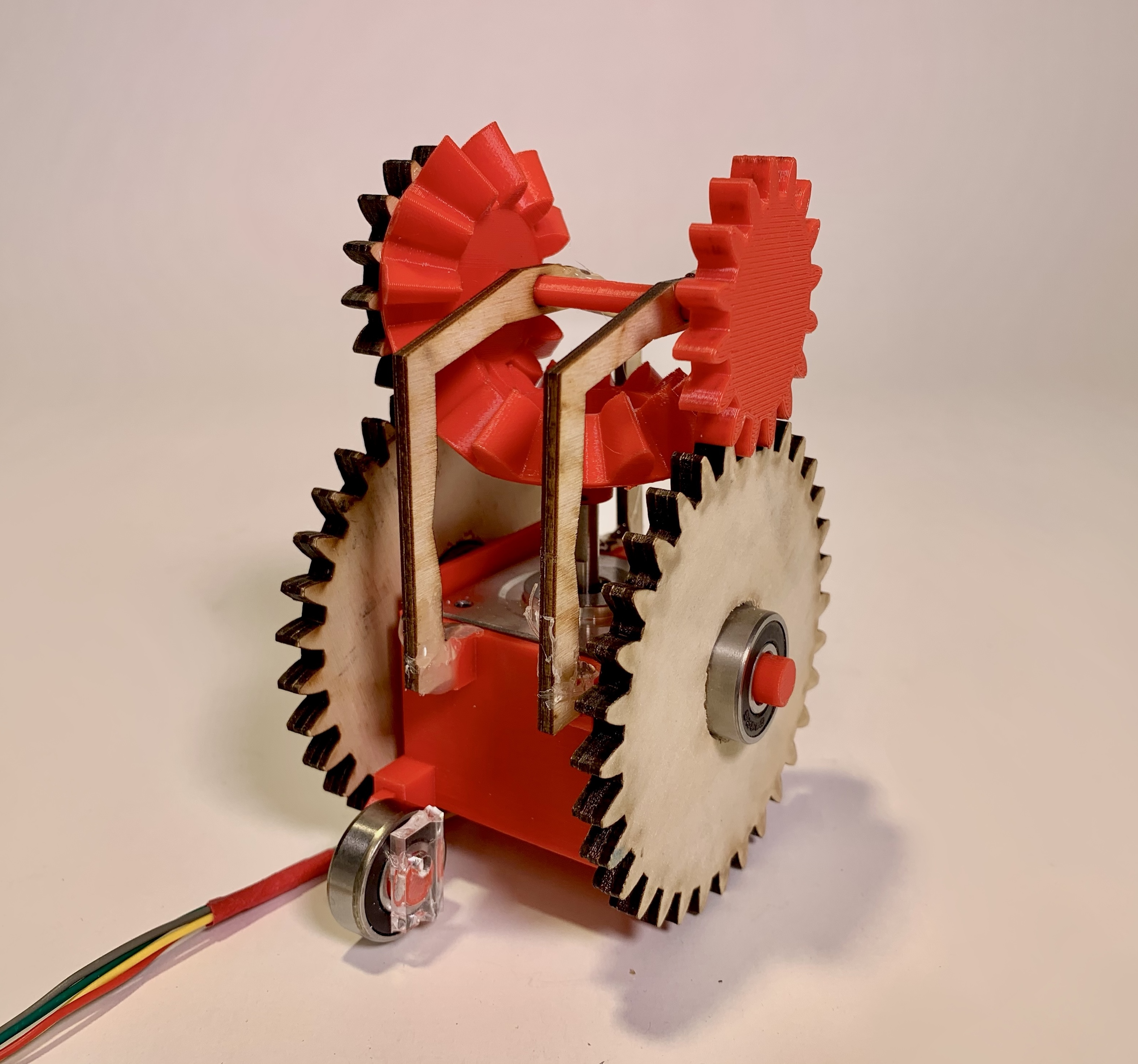
Design - Actuated Mass
We went through 2 prototypes (slides #6 & #7) before reaching our final design. The actuated mass is a stepper motor geared to allow for bi-directional translation with support from a bearing “wheel”. A stepper motor was chosen due to its mass and power rating.
Key design features include:
3D printed motor casing & bearing mount
3D printed bevel gears & shaft to translate stepper motor rotation to a perpendicular axis
3D printed & laser cut spur gears to move the system
Code
The code uses a PID controller on IMU data to rotate the stepper motor counterclockwise or clockwise about the roll axis, as pictured.
Key functions include:
Calibration: takes IMU reading while the wearer is still, determining “balanced” values
Controller: applies PID control with calibrated value as target threshold and real-time IMU values as input
Stepper: takes error from the controller and maps it to CCW or CW steps.

The video on the right shows our 2nd prototype responding to IMU data sent from a sensor mounted on the balance board. As I shift my weight left and right, the prototype travels forwards and backward.
The animation is taken from the Vicon Nexus software. Motion trackers were placed on the main joints of the wearer (legs: red & green lines; body: orange rectangle), and a tracker was placed on the actuated (moving dot connected to the body by orange lines).
As the wear shifts left and right, you can see the mass moving in the opposite direction in response to the movement.
