
Design for Deflection

Software
SolidWorks
Hardware
Waterjet Cutter
Instron Tensile Testing Machine
Design for Deflection is a group project completed for my Fall 2020 Engineering Design II class. We were tasked with designing an aluminum structure given a set of constraints (size, material, etc.) that needed to achieve a certain deflection (0.5 inches), a target spring constant, and minimize weight all while subjected to a 200 lbf load applied by an Instron machine.

FBDs for Castigliano's Analysis
The project culminated in all of the class designs being tested using an Instron tensile machine. My group's design was able to achieve the required deflection with moderate yielding and was also the lightest structure.
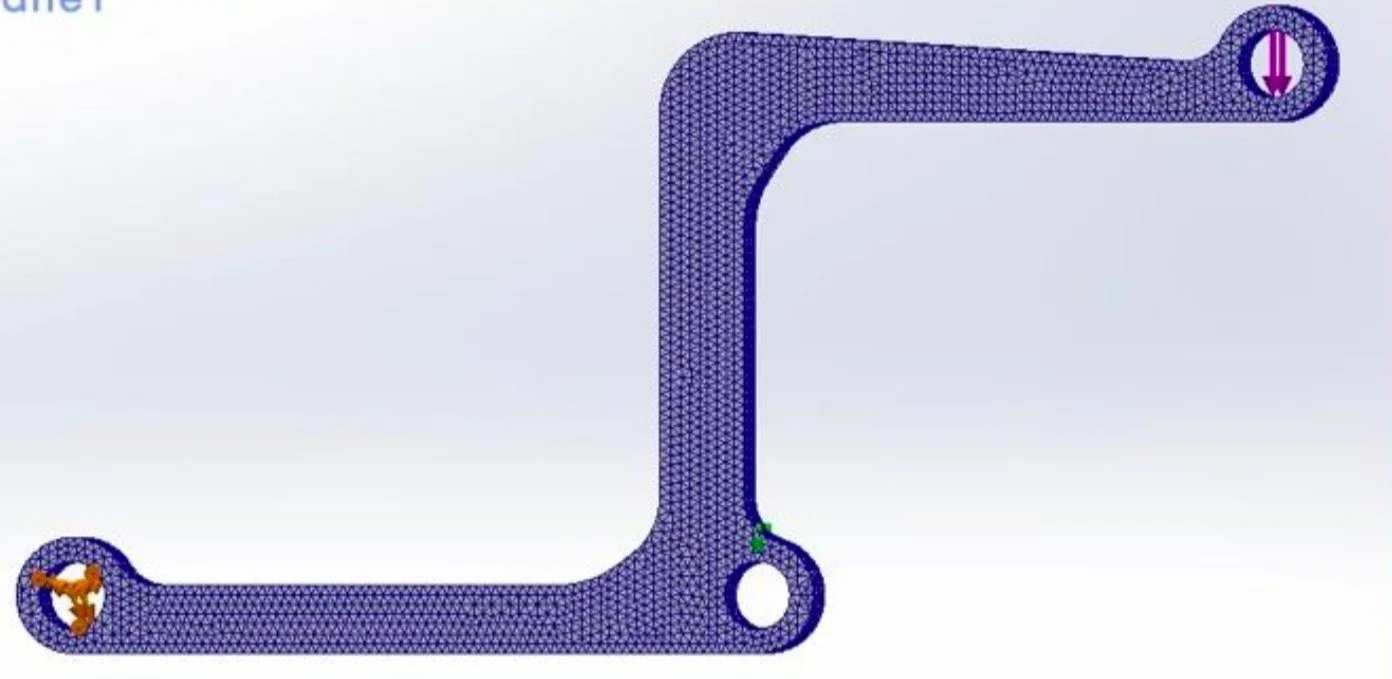
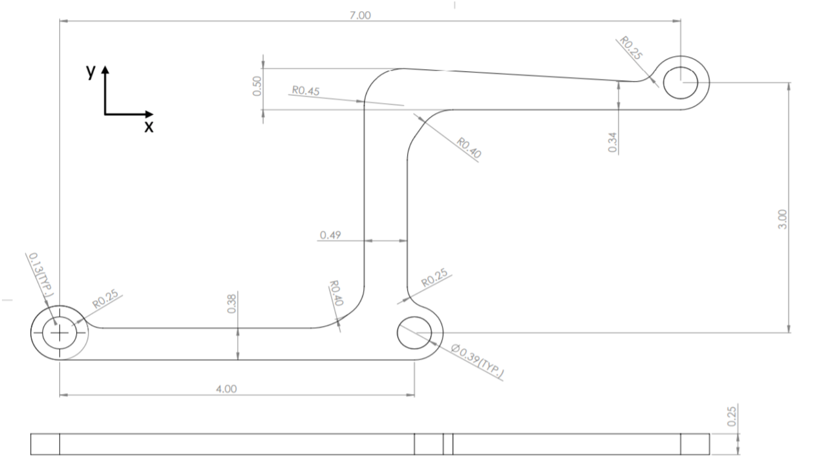
The images at the top show SolidWorks sketches, FEA results, and other renderings of our design. We began our project by analyzing a C-structure with similar dimensions but found that in order to minimize mass while still maintaining a reasonable amount of yield an S-shaped structure was ideal.
We utilized SolidWorks in order to CAD our structure, which was then manufactured using a waterjet cutter. In order to validate our design, we completed an FEA study on SolidWorks and compared those results to results found using Castigliano's Theorem. This allowed us to practice forming a reasonable prediction of a real system’s deflection using two forms of analysis. Additionally, through comparing and evaluating the results from both models, we not only gained a better grasp of deflection but are now able to justify our analytical calculations through simulation.

Experimental Results from Instron Test